


")


Deep Cycle Battery Technology and Charging
VRLA battery
Credit to Wikipedia ®, the free encyclopedia, and various manufacturers A VRLA battery(valve-regulated lead-acid battery), more commonly known as a sealed lead-acid(SLA), GEL, AGM or maintenance free battery, is a type of lead-acid rechargeable battery. Due to their construction, the Gel and AGM types of VRLA can be mounted in any orientation, and do not require constant maintenance. The term “maintenance free” is a misnomer as VRLA batteries still require cleaning and regular functional testing. It means you never have to top them up with water,VRLA batteries have a pressure relief valve which will activate when the battery starts building pressure of hydrogen gas. At high overcharge currents, electrolysis of water occurs, expelling hydrogen and oxygen gas through the battery’s valves. Care must be taken to prevent short circuits and rapid charging. Constant-voltage charging is the usual, most efficient and fastest charging method for VRLA batteries, although other methods can be used. VRLA batteries may be continually “float” charged at around 2.35 volts per cell at 25 °C. Sustained charging at 2.4 V per cell will damage the cells.Absorbed glass mat (AGM)
In an AGM battery, the spaces between the cells is replaced by a glass fibre mat soaked in electrolyte. There is only enough electrolyte in the mat to keep it wet, and if the battery is punctured the electrolyte will not flow out of the mats. Likewise, the mat greatly reduces evaporation, to the point that the batteries do not require periodic refilling of the water. This combination of features allows the battery to be completely sealed, which makes them useful in portable devices and similar roles.
Another advantage to the AGM design is that the electrolyte becomes the separator material, and mechanically strong. This allows the plate stack to be compressed together in the battery shell, slightly increasing energy density compared to liquid or gel versions. AGM batteries often show a characteristic “bulging” in their shells when built in common rectangular shapes.
The mat also significantly prevents stratification, eliminating the need to periodically shake the batteries, boil them, or run an “equalization charge” through them to mix the electrolyte. Stratification is the heavier acid dropping to the bottom of the cell in a wet battery, and is the major cause of failed car batteries. Stratification also causes the upper layers of the battery to become almost completely water, which can freeze in cold weather, AGM’s are significantly less susceptible to damage due to low-temperature use.
AGM batteries are best used in standby power (UPS) use as they do not tolerate repeated deep discharge (<50% capacity) and are damaged by complete discharge.
Gelled electrolytes (GEL)
A silica gelling agent is mixed into the electrolyte. This converts the formerly liquid interior of the cells into a semi-stiff paste, providing many of the same advantages of the AGM. Such designs are even less susceptible to evaporation and are often used in situations where little or no periodic maintenance is possible.
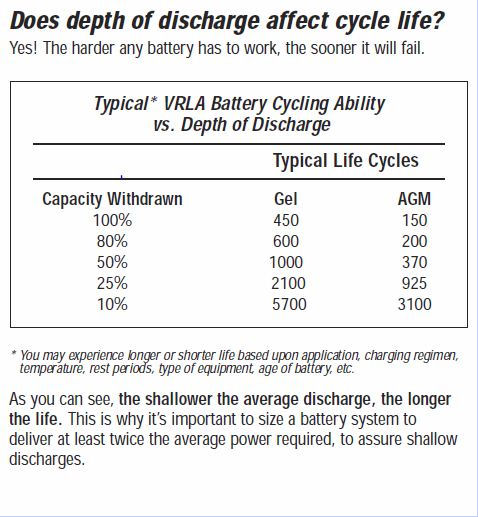
Gel cells also have lower freezing and higher boiling points than the liquid electrolytes used in conventional wet cells and AGM’s, which makes them suitable for use in extreme conditions. Gel cells also tolerate deep discharging much better than AGM cells, and hence have a longer useful life (see table towards end of page).
Deep cycle batteries
Specially designed deep-cycle cells are much less susceptible to degradation due to cycling, and are required for applications where the batteries are regularly discharged, such as photovoltaic systems, electric vehicles (forklift, golf cart, electric cars, mobility scooters and other) and uninterruptible power supplies (UPS). These batteries have thicker plates that can deliver less peak current, but can withstand frequent discharging. Some batteries are designed as a compromise between starter (high-current) and deep cycle batteries. They are able to be discharged to a greater degree than automotive batteries, but less so than deep cycle batteries. They may be referred to as “marine/motorhome” batteries, or “leisure batteries”.
AGM & GEL VRLA batteries
- Have shorter recharge time than flooded lead-acid.
- Cannot tolerate overcharging: overcharging leads to premature failure.
- Have shorter useful life, compared to properly maintained wet-cell battery.
- Discharge significantly less hydrogen gas.
- By nature, are safer for the environment, and safer to use.
- Can be used or positioned in any orientation.
IUoU battery charging
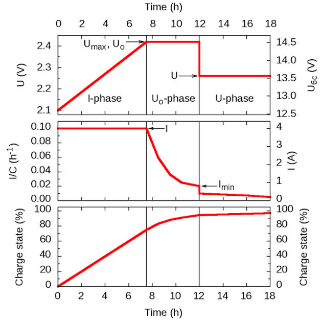
IUoU is the international standard for a lead-acid battery charging procedure that is also known as 3-stage charging,3-phase charging, or 3-step charging. It consists of three phases (or stages), to be executed by a battery charger. The three phases are: I-phase (constant electric current), Uo-phase (constant over voltage), and U-phase (constant voltage). The purpose is to fully charge the battery in a relatively short time without reducing its life span and to indefinitely keep the battery charged as long as the charger is connected.
Stage 1
Stage 1 is called the I-phase,constant-current stage, or bulk charge stage.The charger provides a constant current, typically the maximum current that the charger is capable of producing. As a result of the current, the battery absorbs the charge and its voltage rises. The charger limits the maximum voltage to Umax, a constant or temperature-dependent maximum, typically around 2.4 V per cell. Once the Umax voltage is reached, typically when the battery is charged to 70–80% of its capacity, the charger enters the Uo-phase. In case of a battery that is more than 80% full, this may happen immediately once the charger is switched on.
Stage 2
Stage 2 is called the Uo-phase,constant-voltage boost stage, absorption stage, or topping charge. In this stage, the battery is continued being charged at a constant (over) voltage Uo, but the charge current is decreasing. The decrease is imposed by the battery. The voltage in the Uo-phase is too high to be applied indefinitely (hence, over voltage), but it allows charging the battery fully in a relatively short time. The Uo-phase is concluded when the charge current goes below a threshold Imin, after which the U-phase is entered. This happens when the battery is charged to around 95% of its capacity.
For mobility scooter chargers, this is typically when the charging light turns to green / off.
In some chargers this Uo phase maybe seen as the charge light occasionally turning on for a short time or the green light turning off for a short time.
Stage 3
Stage 3 is called the U-phase or float charge state, the voltage is reduced to a value that is safe to be applied for long periods (indefinitely) without significantly reducing the lifetime of the battery. During this phase, the charge current decreases gradually to a small residual value that compensates for any self-discharge of the battery. (often called “trickle charge” but this is different to old style “wet lead acid battery” trickle chargers that supplied a continual low current but caused high battery voltage and “boiling” (gassing) thus requiring addition of water – this will severely damage VLRA, AGM, GEL batteries)
In some chargers this maybe seen as the charge light occasionally turning on for a short time or the green light turning off for a short time.
Voltages and currents
The current in the I-phase (stage 1) should be chosen depending on the capacity of the battery. In practice, it depends on the capability of the charger. The battery capacity C is expressed in Ah units, typically the C20 value based on a 20-hour discharge time. The charging current (in A units) can be written as C/t where t is a time. For example, for a battery with C = 40 Ah, a current C/(10 hr) (usually written as C/10, omitting the ‘hours’ as time unit) is equal to 4 A. (NOTE : For mobility scooters with 2x 40 AH batteries, C=40 not 80.)
The charging current is a compromise between charging time (favouring high currents), the prevention of damage due to overheating or gassing (favouring low currents), and cost of the charger (favouring low currents). Recommendations for the maximum charging current vary between C/10 and C/2. At high charging currents, active cooling measures may be necessary to prevent overheating.
Mobility Scooter chargers are typically rated at a minimum charging current of C/20 and maximum of C/6.
The voltages in the U and Uo phases (stages 2 and 3) depend on the type of battery and the temperature. Batteries have varying numbers of cells (typically six for to make 12 Volt) and may be flooded cell, AGM (absorbed glass matt), or GEL electrolyte types. The numbers in the table below are for a temperature around 20 °C. For temperatures that deviate more than about 5 °C, a negative correction should be applied of -0.05 mV/°C per cell or -0.3 V/°C for a 12 V (6-cell) battery.
| 3-stage battery charging voltages and currents at 20 °C | ||||||||
|---|---|---|---|---|---|---|---|---|
| Battery type | Stage 1 | Stage 2 | Stage 3 | Stage 3 | ||||
| 6-cell (12 V) | Umax (V) | I | Uo (V) | Imin | U (V) | 24 V | ||
| Wet/flooded | 13.9 | < C/5 | 14.5 | I/10 | 13.6 | 27.2 | ||
| 14.8 | < C/2 | 14.8–15.0 | C/100 | 13.5–13.8 | 27.0–27.6 | |||
| AGM | 13.9 | < C/5 | 14.5 | I/10 | 13.6 | 27.2 | ||
| 14.1 | < C/2 | 14.1–14.4 | C/100 | 13.6–13.8 | 27.2–27.6 | |||
| GEL | 13.9 | < C/5 | 14.1 | I/10 | 13.6 | 27.2 | ||
| 14.1 | < C/2 | 14.1–14.4 | C/100 | 13.5–13.8 | 27.0–27.6 | |||
| State of Charge as Related to Open Circuit Voltage * | |||||||||||
|---|---|---|---|---|---|---|---|---|---|---|---|
| Open-Circuit Voltage | |||||||||||
| % Charge | 12v | 24v | |||||||||
| 100 | 12.73 | 25.46 | |||||||||
| 90 | 12.62 | 25.24 | |||||||||
| 80 | 12.50 | 25.00 | |||||||||
| 70 | 12.37 | 24.74 | |||||||||
| 60 | 12.27 | 24.48 | |||||||||
| 50 | 12.10 | 24.20 | |||||||||
| 40 | 11.89 | 23.92 | |||||||||
| 30 | 11.81 | 23.63 | |||||||||
| 20 | 11.66 | 23.32 | |||||||||
| 10 | 11.51 | 23.02 | |||||||||
* When testing a battery for state of charge (SOC), or state of health (SOH that is its able capacity against its rated capacity), with an algorithm battery tester, the surface charge must be removed from a recently charged battery, by applying a load of say C/10 for 5 mins, so in effect the 100% charge voltage will be 12.7 – 12.8 Volt.
AGM and GEL batteries must not be load tested ! Use an algorithm programmed tester or battery capacity discharger.Equalisation (ensuring uniform strength of electrolyte) is not required for AGM or GEL batteries as stratification does not occur.Sulphation of batteries will occur when the 12 V battery voltage drops below 12.5 Volts.Sulphation forms on the battery plates reducing and eventually destroying the ability of the battery to store energy.
There are devices for removing hard sulphation, but the best practice is preventing formation by proper battery care and recharging after a discharge cycle. These devices appear to not work with AGM or GEL batteries.Sulphation is the main reason a significant portion of lead acid batteries don’t attain their chemical life span. So,keep the battery fully charged !
| Charger Voltage Settings for VRLA Batteries | System Voltage | |
|---|---|---|
| Charger Voltage Setting | 12v | 24v |
| Bulk Charge | 14.4 | 28.8 |
| Continuous Float Charge – Gel | 13.4 | 26.8 |
| Continuous Float Charge – AGM | 13.5 | 27.0 |
| Continuous Float Charge – Flooded | 13.9 | 27.8 |
| Open circuit full charge | 12.6 | 25.2 |
| Open circuit full discharge | 11.7 | 23.4 |
| Loaded at full discharge | 10.5 | 21.0 |
| Note : Values for Li-ion battery chargers are different, requiring about 2% more voltage to fully charge the battery. | ||
DISCHARGING
Discharging batteries is entirely a function of your particular application.However, below is list of helpful items:- Shallow discharges will result in a longer battery life.
- 50% (or less) discharges are recommended, especially for AGM batteries.
- 80% discharge is the maximum safe discharge, and only for GEL batteries.
- Do not fully discharge flooded batteries (80% or more). This will damage (or kill) the battery.
- Many experts recommend operating batteries only between full and 50% to 85% of full charge.
- Do not leave batteries deeply discharged for any length of time.
- Lead acid batteries do not develop a memory and do not need to be fully discharged before recharging, in fact as written above, this will damage any battery.
- Batteries should be charged after each period of use.
- Batteries that charge up but cannot support a load are most likely bad or worn and should be tested. VLRA batteries (AGM and GEL) should not be tested by load method as this draws excessive current that may damage the battery due to gassing. A “no-load” tester using algorithms is required, or time /current discharge machinery. (We have such testing equipment)
Self Discharging
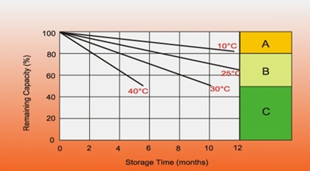
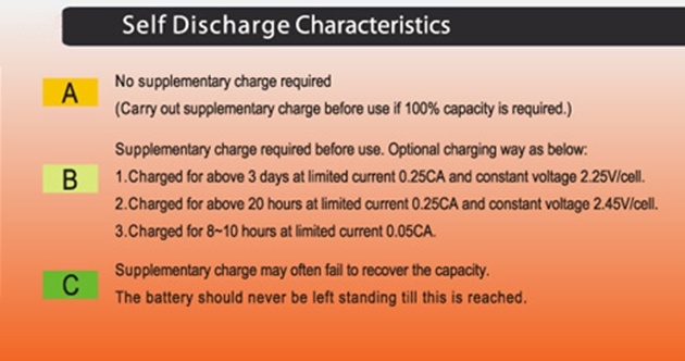
Batteries self discharge over time, eg while in storage / not in use.Many factors are involved in self discharge rates, but temperature and battery SOH (state of health) are the most important.
The best option is to not allow self discharge or to “top up” often.The following table shows some principles
Now what does all that mean ?
In a nutshell,
1 – all battery chargers today are / should be built to an international standard to charge batteries in such a manner that the batteries will have maximum life.Caveat : cheap battery chargers do not have sufficient electronic components to accurately maintain charging voltages and currents. This may turn out to be a very expensive option, as battery life will be shortened, sometimes significantly.
2 – all batteries lead acid should be charged after every use, and as soon as possible
3 – the charger should remain on long enough to fully charge the battery – this can be as long as 12-24 hours
4 – it is recommended to leave the charger on overnight to ensure fully charged batteries
5 – the charger may safely remain on indefinitely (NOT Li Ion) (residual power used is 0-3 Watt)
6 – it is recommended to recharge the battery fortnightly or monthly if not being used and the charger is disconnected
7 – batteries do not like extremes of temperature, 45and especially not hot temperatures
8 – the best thing to do is to :
Recharge the lead acid battery as soon as possible and to Leave the charger on and to Keep the temperature as close to 25°C as possible.
The above is a simplified report on the complex topic of Lead Acid Battery technology of various types, including use, charging and discharging.If you have any other questions or problems not covered here, just give us a phone call : (03) 7036 4440 or “Email Mobility Scooters for Hire” Lithium Ion Battery Charging Need a battery charger ? – The latest technology in BATTERY CHARGERS